Disassembly and Maintenance of Rack 1 (CD) — Removing a Stuck Leader Card + Processing Rack Cleaning Procedure
Equipment: Noritsu V50 (QSF-V30/V50/V100 family, negative color film processor) Unit: Rack 1 = CD rack (Color Developer) — the first and longest rack in the developer section chain Situation: a leader card is stuck in the middle of the rack, the rack is still sitting in the tank with working CD solution Sources: Noritsu QSF maintenance manual (§2.2, §8.2), QSF service manual, QSF installation manual, QSF operator’s manual (Basic)
Quick notes
- The rack is still in the tank with CD solution — drain the solution and remove the rack first, then disassemble the side plate. Gloves help with the solution.
- V50: film travel time ≈ 4 minutes for 2000 mm (V30 ≈ 7 min, V100 ≈ 2 min) — if the card has been stationary longer than this, it’s a confirmed jam.
- Why Rack 1 is the largest: racks are installed “in sequence according to number beginning with CD”, and CD (developer) is the longest processing stage, so its rack is physically longer than the others.
1. Preparation (mandatory before any intervention)
Source: QSF maintenance manual, §2.2 “PRE-MAINTENANCE PROCEDURES”, pp. 2-3 — 2-4
Step 1 — Make sure no film is currently being processed
Bring up the DEVELOPMENT or FILM POSITION display and confirm no film is being processed. If something is still being processed, wait until it comes out of the dryer unit.
Step 2 — Set the upper cover to ventilation
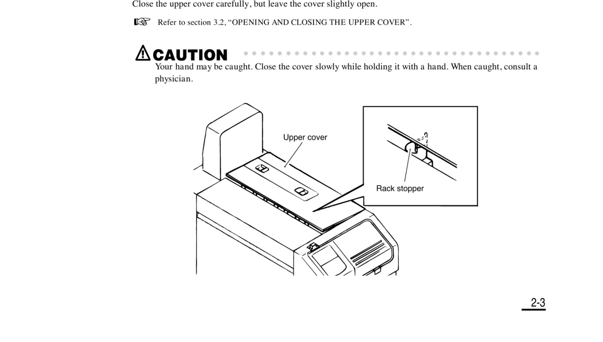
Remove the negative stocker, open the upper cover, and release the rack stoppers. Carefully close the cover, but leave it slightly open.
Step 3 — Turn off the power
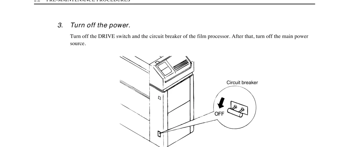
Turn off the DRIVE switch and the circuit breaker of the processor. Then turn off the main power source.
2. Removing the stuck leader card from Rack 1 (CD)
2.1 Draining the CD solution (required before removing the rack)
Source: QSF maintenance manual, §8.2.1 “Draining the processing solution (CD)”, p. 8-4
- Remove the replenisher tank cover (see manual section 3.4, “REMOVING AND ATTACHING THE REPLENISHER TANK COVER”).
- Prepare a container for the solution. Connect the standard vinyl hose to the solution outlet. Open the drain valve to drain the CD solution.
- Close the drain valve.
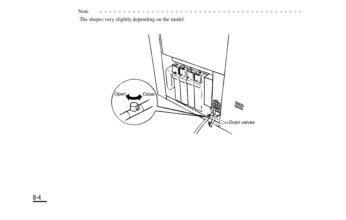
Note: valve shapes may vary slightly depending on the model/unit variant.
2.2 Removing the guides and the rack
Source: QSF maintenance manual, §8.2.3 “Removing the processing racks and squeegee rack”, pp. 8-6 — 8-7
- Fully open the upper cover (manual section 3.2).
- Remove the inlet guide and the upper turn guides.
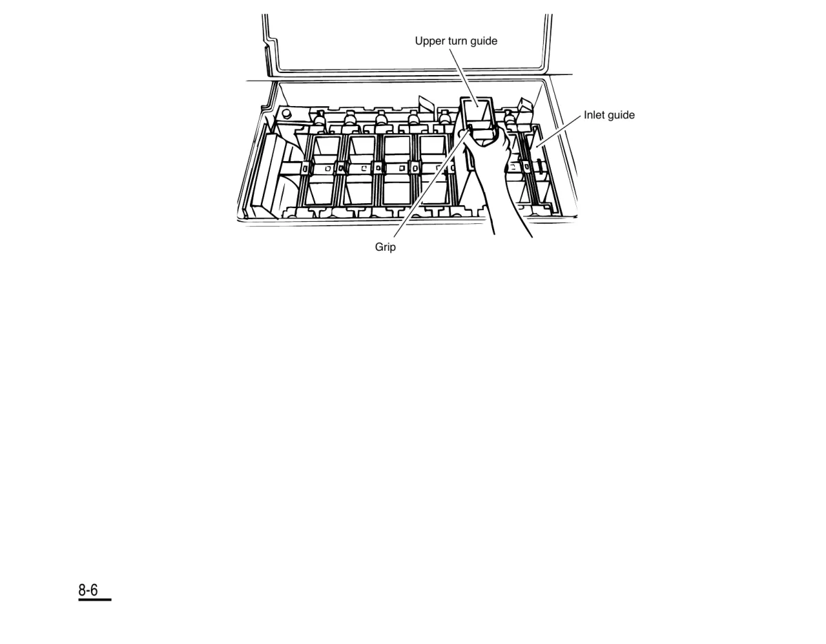
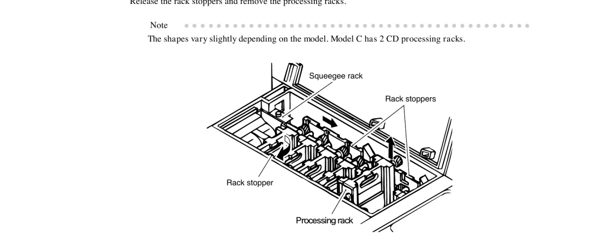
- Release the rack stoppers and remove the processing rack (Rack 1 / CD) from the tank.

Note from the manual: “The shapes vary slightly depending on the model. Model C has 2 CD processing racks.” — if you have Model C, keep in mind there may be two CD racks.
2.3 Rack No.1 (CD) construction — what’s inside
Source: Noritsu QSF parts list, sections 19 “RACK (No.1)” and 20 “RACK (No.1)”, pp. 53-56 — exact parts breakdown for this rack.
The rack body is built from two plastic side plates:
- RACK PLATE IN (C205503-01) — inner side plate
- RACK PLATE OUT (D203275-01) — outer side plate
Between them, mounted on shafts (DRIVE SHAFT A229790-01 and others), are roller/gear pairs:
- DRIVE GEAR (A138007-01) — drive gear
- IDLE GEAR (A137314-01, A229788-01, A128813-01) — idler gears (transfer rotation between sections)
- SQUEEGEE DRIVE GEAR / SQUEEGEE IDLE GEAR / SQUEEGEE ROLLER GEAR — squeegee roller gears
- SPROCKET (A509990-01, A509991-00) — sprockets that pull the perforated film/card
- GUIDE, FILM (A239395-01, A239397-01, A232579-01) — pivoting guide flaps, this is where the card most often jams
- SPRING (A203800-01) — roller pair pressure spring
- BUSHING (A128559-01, A206140-01, A206141-01, A229792-01) — shaft bushings
- Shafts and gears are secured with an E-RING (H005019-00) or a retaining RING #4 (A004980-01) — a standard snap ring seated in a groove on the shaft.
2.4 Opening the side plate to free the card
- Lay the removed rack down with the internal side up (the side showing the rollers and gears), or in the rack transportation tank.
- On the RACK PLATE OUT side plate, find the section that lines up with where the card is jammed — each roller pair’s shaft carries a retaining ring (E-ring or RING #4) on the outside of the plate.
- Remove the retaining ring on the relevant shaft — pry it off with a small flat screwdriver or snap-ring pliers, hooking the slot in the ring.
- With the ring off, the gear/roller on that shaft is no longer axially fixed — slide it along the shaft toward the outer plate; this relieves the pinch and opens a gap.
- If needed, remove the second gear of the pair (top or bottom) the same way, so the rollers fully separate and the card comes free without tension.
- If the card is caught in a guide flap (GUIDE, FILM) rather than a roller pair — these guides are spring-loaded and pivot on their axis; pry the guide away from the shaft by hand or with a flat screwdriver inserted into the side gap, then pull the card free.
- Pull the card out along the film’s direction of travel (not sideways, and don’t force a bend).
- Slide the removed gears/rollers back onto the shaft in their original position and snap the retaining ring (E-ring/RING #4) back into the shaft’s groove.
- Turn the freed section of the rack by hand via the gear — the rollers should spin freely with no play or binding, and the retaining ring should sit flush in its groove.
If a gear or roller turns out cracked or chipped during removal — per the parts list these are separately orderable items (e.g.
A138007-01 DRIVE GEAR,Z009020-01 ROLLER UNIT), so replacing the whole rack usually isn’t necessary.
3. Full cleaning of Rack 1 during scheduled maintenance
Source: QSF maintenance manual, §8.2 “CLEANING THE PROCESSING TANK”, pp. 8-1 — 8-10. Performed during a full solution replacement once the photosensitive material manufacturer’s designated period expires.
8.2.1 Draining the CD solution
See section 2.1 above — identical procedure.
8.2.2 Draining the BL, FIX & STB solutions
The valves for these solutions are located on the dryer unit, not on the processor itself:
- Remove the rear cover (Models A and B) or the dryer unit cover (Model C).
- Connect the vinyl hose to the solution outlet, open the valve, drain the solution.
- Close the valve.
- Repeat for each remaining solution.
8.2.3 Removing the racks and squeegee rack
See section 2.2 above.
8.2.4 Cleaning the tank
- Connect the vinyl hose to the tank’s solution outlet so the cleaning water flows into a separate container.
- Open the tank’s drain valve for cleaning.
- Wash the inside of the tank with water, removing dirt with a tank cleaning brush (sold separately). If crystals or scale are visible at the top of the overflow pipe, carefully clean the pipe with a small brush.
- Close the drain valve.
- Repeat steps 1–4 for each tank.
- Reattach the replenisher tank cover and rear cover (Models A/B) or the dryer unit cover (Model C).
8.2.5 Pouring the solutions
Pour each pre-mixed solution into its corresponding tank. If the rack is already installed, measure and pour the required amount so the solution reaches the top of the overflow pipe.
Important: make sure the drain valve is closed before pouring the solution.
8.2.6 Reinstalling the racks and squeegee rack
- Hold the rack by its grip and reinstall it in the tank without spilling solution into an adjacent tank (mixed solutions become unusable).
- Attach the squeegee rack.
- Secure all rack stoppers.
- Reattach the inlet guide and upper turn guides.
- Close the upper cover (manual section 3.2).
Technician checklist
- Confirmed no film is currently being processed
- Upper cover left slightly open for ventilation, rack stoppers released
- DRIVE switch and circuit breaker turned off, main power disconnected
- CD solution drained from Rack 1
- Inlet guide and upper turn guides removed
- Rack 1 (CD) removed from the tank and placed in the transportation tray
- Leader card extracted without damaging rollers/gears
- Rollers and gears in the affected section turned by hand — rotate smoothly
- Rack reinstalled without solution overflow into an adjacent tank
- Squeegee rack installed, all rack stoppers secured
- Inlet guide and upper turn guides reattached
- Upper cover closed
- Power restored, test run performed (e.g., §3.1.10 “Passing test of leader card” — a control run of a fresh leader card through the whole path to verify the transport is working before feeding real customer film)
Additional: leader card test run after repair
Source: QSF operator’s manual (Basic), §3.1.10 “Passing test of leader card”
After restoring the rack to working order, it’s recommended to run the official leader card passing test before processing any real customer film:
- Open the loading cover using the open button.
- The display will show “INSERT LEADER CARD” — insert the leader card to the required position.
- Close the loading cover.
- After starting, “LEADER CARD BEING FED” will be displayed — the card travels through the entire path (CD -> BL -> FIX -> STB -> dryer).
- The card’s current position is shown at the bottom-left of the display. When the highlight reaches “D” (right end) and the card is ejected from the dryer unit, press YES.
- The “LEADER CARD TEST FINISHED?” screen will appear — confirm the test is complete.
If the card jams again in the same location during this test, the rack assembly is most likely mechanically damaged (a bent guide, a damaged gear) and requires replacement of that part of the rack rather than another manual extraction attempt.