Full test procedure: heater not heating, temperature stuck then dropping
Original question (paraphrased):
On a Noritsu V50, the CD tank heater doesn’t seem to be heating the solution. The temperature climbs to a certain value, gets stuck there, stops moving, and then starts dropping. Write a full manual for testing this: which circuit chains to check, which board connects to what, what resistance the heaters should have, what to do if the wrong heaters (from another model) are installed, and how critical that is.
Equipment: Noritsu V50 (QSF-V30/V50/V100 family, negative color film processor) Symptom: CD solution temperature rises to a point, plateaus, then declines — heater is not maintaining setpoint Source: Noritsu QSF service manual — Troubleshooting section, Error No. 022 “SOLUTION TEMP. ERROR” (pp. 184-190), Printed Circuit Boards section (p. 287)
1. What the symptom means
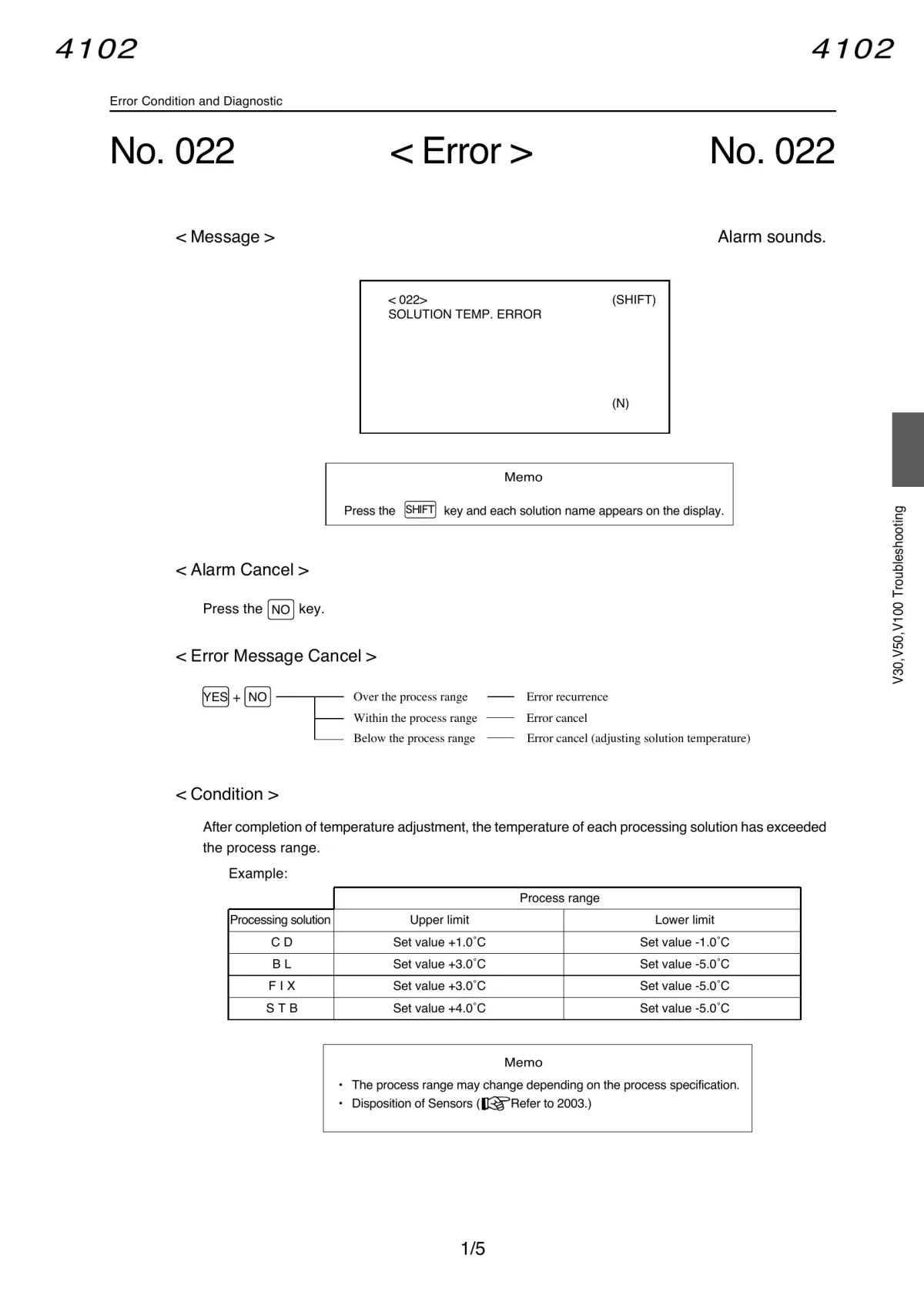
“Temperature climbs, plateaus below setpoint, then drops” is the classic signature of a heater that is either underpowered, intermittent, or has failed open — not a thermosensor problem (a bad sensor usually gives a wildly wrong or frozen reading, not a real temperature that visibly plateaus and falls). The system’s own error logic backs this up: it treats this exact condition as error No. 022 “SOLUTION TEMP. ERROR” once the reading falls outside the allowed process range for CD.
Process range (V30/V50/V100, all models, per process specification):
| Solution | Upper limit | Lower limit |
|---|---|---|
| CD | Set value +1.0°C | Set value -1.0°C |
| BL | Set value +3.0°C | Set value -5.0°C |
| FIX | Set value +3.0°C | Set value -5.0°C |
| STB | Set value +4.0°C | Set value -5.0°C |
Note how narrow the CD tolerance is (±1.0°C) compared to the others — this is why CD heater problems surface as a hard error very quickly, while the same fault on BL/FIX/STB might go unnoticed longer.

2. Where the heater circuit physically lives
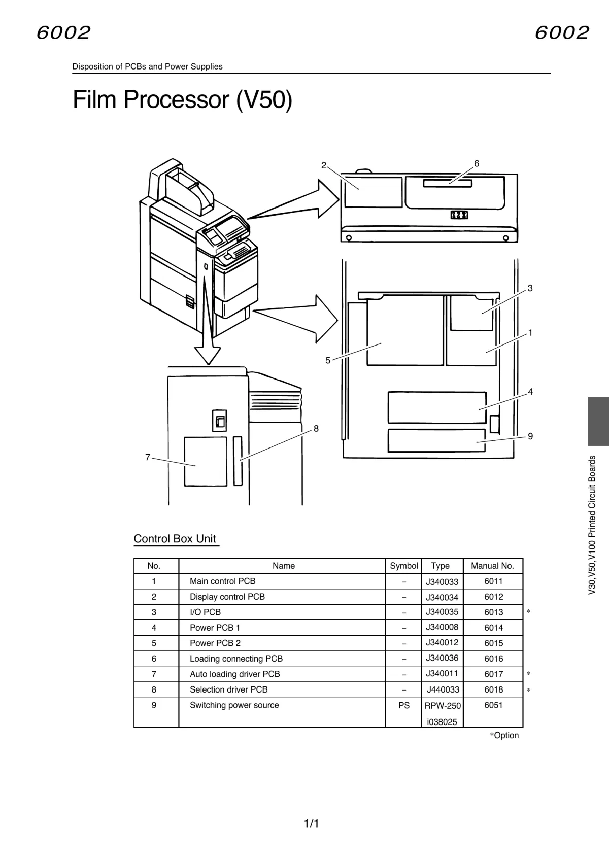
Source: QSF Service Manual, “Disposition of PCBs and Power Supplies”, Film Processor (V50), p. 287
The V50 control box contains these boards, numbered as shown in the diagram below:
| # | Board | Type | Manual ref. |
|---|---|---|---|
| 1 | Main control PCB | J340033 | 6011 |
| 2 | Display control PCB | J340034 | 6012 |
| 3 | I/O PCB (option) | J340035 | 6013 |
| 4 | Power PCB 1 | J340008 | 6014 |
| 5 | Power PCB 2 | J340012 | 6015 |
| 6 | Loading connecting PCB | J340036 | 6016 |
| 7 | Auto loading driver PCB (option) | J340011 | 6017 |
| 8 | Selection driver PCB (option) | J440033 | 6018 |
| 9 | Switching power source | RPW-250 / i038025 | 6051 |
The heater circuit involves three boards, in this chain:
Main control PCB  <->  Power PCB 2  <->  Power PCB 1  --[fuse]-->  Heater (physical element in tank)
        ^                                        ^
        |                                        |
  (decision logic:                        (switches mains power
   compares thermosensor                   to the heater via
   reading vs setpoint,                    fuses F1-F4/F10/F11)
   drives Power PCB 2)
- Main control PCB reads the thermosensor and decides whether the heater should be on.
- Power PCB 2 relays that signal toward Power PCB 1.
- Power PCB 1 actually switches mains power to the heater, protected by dedicated fuses per solution.
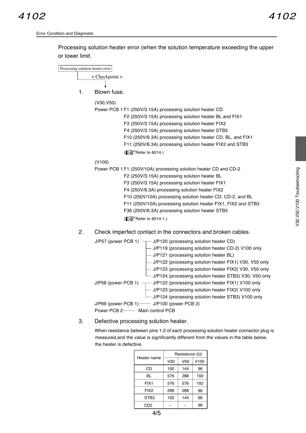
3. Fuses — which one protects which heater (V30/V50)
Power PCB 1, all values 250V rating:
| Fuse | Rating | Protects |
|---|---|---|
| F1 | 3.15A | CD heater |
| F2 | 3.15A | BL and FIX1 heaters |
| F3 | 3.15A | FIX2 heater |
| F4 | 3.15A | STB3 heater |
| F10 | 6.3A | CD, BL, and FIX1 (combined/upstream) |
| F11 | 6.3A | FIX2 and STB3 (combined/upstream) |
For a CD heater problem specifically: check F1 first, then F10 (the shared upstream fuse covering CD along with BL/FIX1).
Note: the V100 uses different fuse numbers/ratings (F1 is 10A and covers CD+CD-2, plus F36 exists for STB3) — don’t cross-reference V100 fuse values onto a V50 unit.
4. Connector chain to trace with a multimeter
Source: QSF Service Manual, Error No. 022, Checkpoint 2 (heater), p. 187
J/P57 (Power PCB 1) --+-- J/P120  processing solution heater CD
                       +-- J/P121  processing solution heater BL
                       +-- J/P122  processing solution heater FIX1   (V30/V50 only)
                       +-- J/P123  processing solution heater FIX2   (V30/V50 only)
                       +-- J/P124  processing solution heater STB3   (V30/V50 only)

J/P69 (Power PCB 1) -- J/P100 (Power PCB 2)
Power PCB 2 -- Main control PCB
Practical test order:
- Power off, open the control box, locate Power PCB 1.
- Visually check F1 (and F10) — look for a visibly blown fuse or test continuity with the fuse removed.
- Check J/P57 -> J/P120 for firm seating and no corrosion/broken pins.
- With the heater connector unplugged, measure resistance across the CD heater’s own two pins (not through the board) — see the table below.
- Check J/P69 -> J/P100 (Power PCB 1 to Power PCB 2) and the Power PCB 2 -> Main control PCB link for continuity if steps 1-4 come back clean.
5. Heater resistance table — all solutions, all models
Source: QSF Service Manual, Error No. 022, Checkpoint 3, p. 187
Measured between pins 1-2 at the plug side of each heater connector:
| Heater | V30 | V50 | V100 |
|---|---|---|---|
| CD | 192 Ω | 144 Ω | 96 Ω |
| BL | 576 Ω | 288 Ω | 192 Ω |
| FIX1 | 576 Ω | 576 Ω | 192 Ω |
| FIX2 | 288 Ω | 288 Ω | 96 Ω |
| STB3 | 192 Ω | 144 Ω | 96 Ω |
| CD2 | — | — | 96 Ω |
If the measured value is significantly different from the table — the heater is defective (open, shorted, or partially failed) and must be replaced.
6. Thermosensor — rule it out as a secondary cause
Even though the symptom pattern (plateau then decline) points to the heater rather than the sensor, confirm the sensor isn’t also contributing, since a dirty/misreading sensor can make the control loop under-drive a perfectly good heater.
Connector chain:
J/P8 (Main control PCB) --+-- J/P154  thermosensor CD
                            +-- J/P155  thermosensor BL
                            +-- J/P156  thermosensor FIX1
                            +-- J/P157  thermosensor FIX2
                            +-- J/P160  thermosensor STB
Resistance table (CD/BL/FIX1/FIX2/STB share one table):
| Actual temperature (°C) | Resistance (kΩ) |
|---|---|
| 10 | 20.66 |
| 20 | 12.64 |
| 30 | 7.97 |
| 35 | 6.39 |
| 38 | 5.62 |
| 40 | 5.16 |
| 45 | 4.20 |
If the thermosensor is dirty, clean it. If resistance is off vs. the actual measured solution temperature, replace the sensor.
7. Safety thermostat — check if error No.023 also appears
If you additionally see error No.023 “SOLN. S-THERMO. ACTIVATED”, that’s a separate, independent safety cutoff — not the same fault as the heater/thermosensor chain, but it can look like “heater doesn’t heat” if it has already tripped and shut things down upstream.
How it works: each solution has its own safety thermostat + level float switch. If it trips on one solution, every solution downstream in the chain is also shut off (e.g., if BL’s thermostat trips, FIX1 onward are cut too).
- OPEN (OFF) at 46 ± 3°C
- CLOSE (ON, normal) at 36 ± 3°C
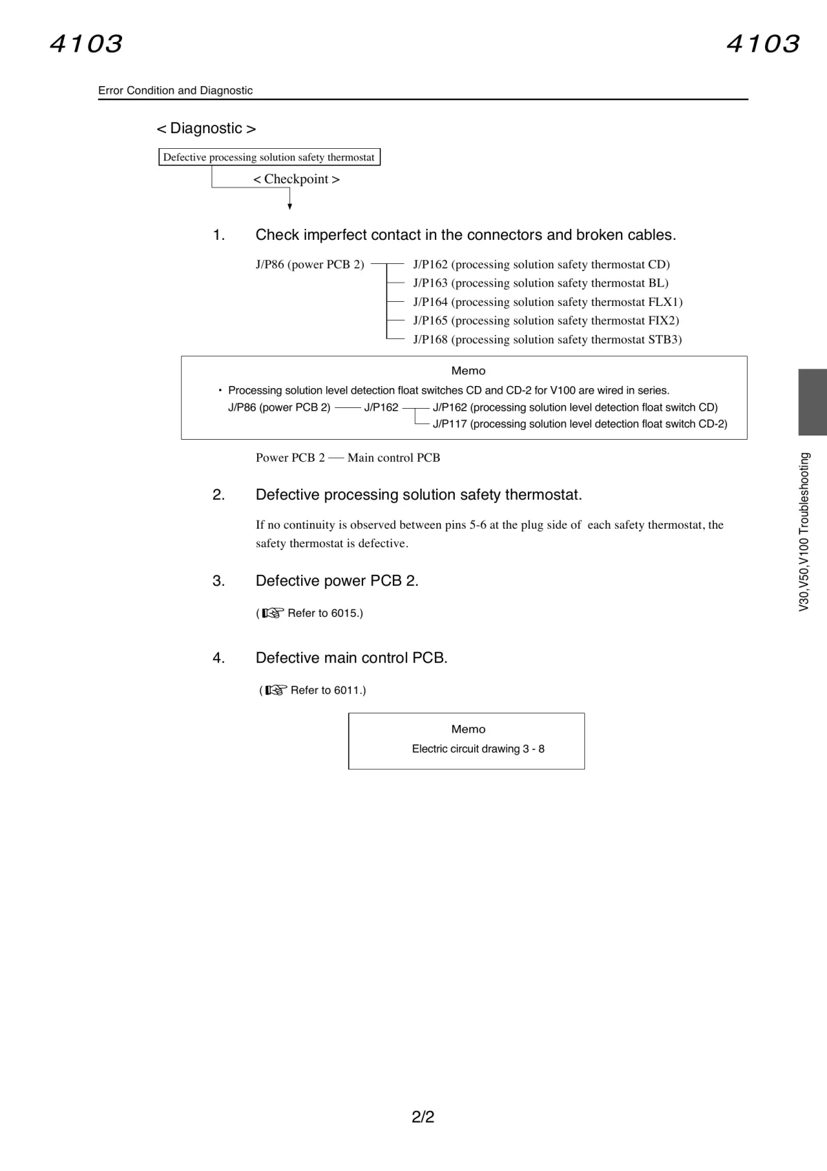
Connector chain:
J/P86 (Power PCB 2) --+-- J/P162  safety thermostat CD
                        +-- J/P163  safety thermostat BL
                        +-- J/P164  safety thermostat FIX1
                        +-- J/P165  safety thermostat FIX2
                        +-- J/P168  safety thermostat STB3
Test: no continuity between pins 5-6 at the plug side = thermostat is defective.
8. Full test sequence (do this in order)
- Power down — turn off circuit breaker and main power before opening any covers.
- Check error history/current display for No.022 (heater/process range) and No.023 (safety thermostat) — these tell you which branch of the diagnostic tree to follow.
- Visual + continuity check on fuses F1 and F10 (Power PCB 1).
- Unplug the CD heater connector and measure its resistance directly — compare to 144 Ω (V50). This is the single most important measurement for this symptom, since a heater failing open-circuit under load (intermittent contact inside the element) produces exactly the “climbs, plateaus, falls” pattern as it cycles between conducting and not.
- Check J/P57->J/P120 and J/P69->J/P100 connector chain for corrosion/looseness.
- Check the thermosensor (J/P8->J/P154, resistance table) to rule out a sensor reporting a false plateau.
- Check the safety thermostat (J/P86->J/P162, continuity 5-6) if error No.023 has appeared at any point — a tripped thermostat cuts the heater regardless of its own health.
- If all of the above check out electrically and the heater still underperforms — suspect Power PCB 1 (defective triac/relay driving the CD output specifically), then Power PCB 2, then Main control PCB, in that order (this matches the manual’s own checkpoint priority — physical/consumable parts first, boards last).
9. Wrong-model heaters installed — how critical is it, really
If you find a heater in place whose resistance doesn’t match the V50 table (e.g., it reads close to a V30 or V100 value instead of the correct V50 value), here’s what that means and how urgent it is:
Why it matters: heater wattage is inversely proportional to resistance at a fixed voltage (P = U²/R). A heater built for a different model in the same physical socket will run at the wrong power level for that tank:
| If a heater rated for… | …is installed in a V50 CD socket (needs 144 Ω) | Effect |
|---|---|---|
| V30 (192 Ω) | ~25% less power than correct | Slower heating, may struggle to keep up on a large batch — annoying but survivable |
| V100 (96 Ω) | ~50% more power than correct | Faster heating, but overshoot risk and higher steady-state current draw on the fuse/circuit |
How critical this is, concretely:
- For CD specifically — this is the least forgiving tank to get wrong. The process range is only ±1.0°C. A heater running meaningfully hotter or cooler than designed makes the control loop hunt harder around the setpoint, increasing the chance of tripping error No.022 repeatedly even when nothing else is wrong.
- A too-low-resistance (higher-wattage) heater is the more dangerous mismatch — it pushes more current through wiring, connectors, and the fuse than the circuit was designed for that position. The fuse (F1, 3.15A on V50) is your safety margin; running a heater that draws meaningfully more current than the V50 design intended erodes that margin. It won’t necessarily blow the fuse immediately, but it removes headroom that was there for a reason.
- A too-high-resistance (lower-wattage) heater is safer electrically but functionally means the tank may never reach setpoint under demand, which is operationally the same failure being troubleshot here (temperature plateaus below target) — so an under-powered substitute heater can itself be the root cause of this exact symptom.
- This is not a “just leave it, it still works” situation for CD. Given the ±1.0°C tolerance and CD’s role in actually forming the image (unlike STB, which has much wider tolerance and no direct effect on image formation), a wrong-resistance heater in CD should be treated as a confirmed defect to replace, not a tolerable substitution — even if it appears to “mostly” work.
- Practical fix: measure the resistance directly (per the table above) — if it doesn’t match 144 Ω for CD, source and install the correct V50-spec heater. Don’t try to compensate electrically (e.g., adding series resistance) — that turns one component with a known failure mode into two, in a wet chemical tank, for no real gain.
Quick-reference summary
| Check | Reference | Pass criteria |
|---|---|---|
| Fuse F1 (CD) | Power PCB 1 | Continuous, not blown |
| Fuse F10 (CD/BL/FIX1 shared) | Power PCB 1 | Continuous, not blown |
| CD heater resistance | J/P120 connector, pins 1-2 | 144 Ω (V50) |
| CD thermosensor resistance | J/P154 connector, pins 1-2 | Per temp/resistance table |
| CD safety thermostat | J/P162 connector, pins 5-6 | Continuity present (not tripped) |
| Connector chain | J/P57->J/P120, J/P69->J/P100 | Firm seating, no corrosion |
| Board-level (last resort) | Power PCB 1 -> Power PCB 2 -> Main control PCB | Replace in this order if all else checks out |