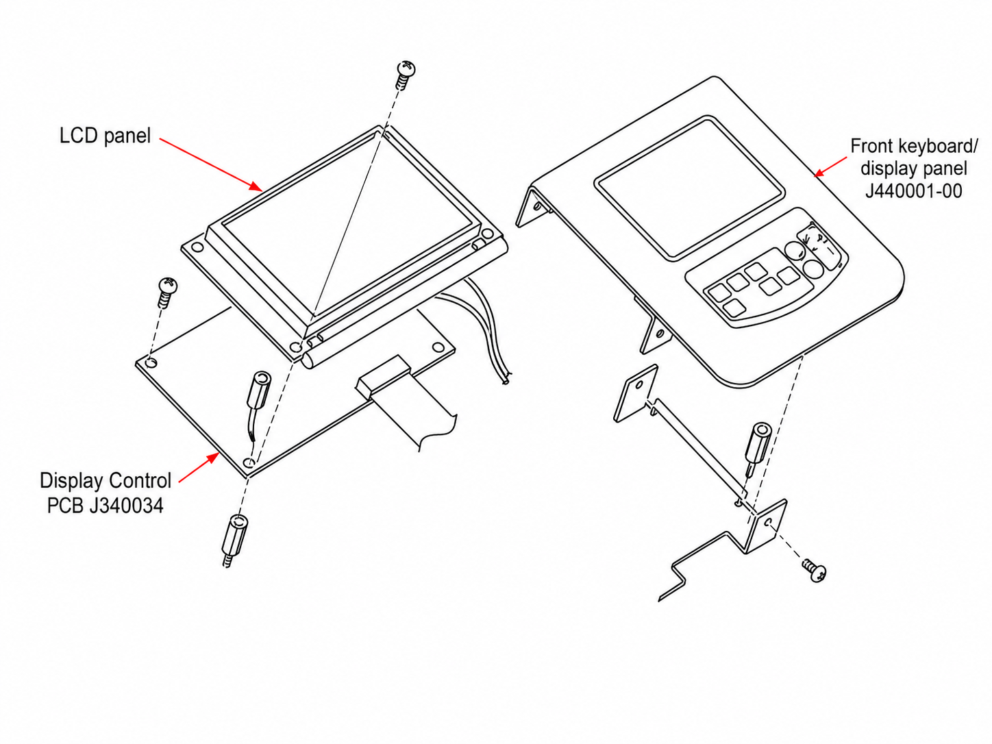
The keypad used in the Noritsu QSF-V50 is wired as a button matrix. Each button connects two lines of the same 8-pin connector when pressed.
This makes the keypad easy to test with a standard multimeter. By checking which connector pins are connected for each pressed button, you can determine whether the fault is in the membrane keypad, the connector, or the Display Control PCB.
Keypad assembly

- Keyboard: J440001
- Display Control PCB: J340034
- Keyboard connector: J/P15
- Connector type: FDZ-8L
- Used contacts: pins 1-7
- Unused contact: pin 8
The matrix is shown in the QSF service manual, wiring diagram 3-12.
Button matrix pinout
The following two pins must have continuity while the corresponding button is pressed:
| Pressed button | Pins that must have continuity |
|---|---|
| MODE | 1-5 |
| SHIFT | 2-5 |
| PLUS | 3-5 |
| MINUS | 4-5 |
| YES | 1-6 |
| NO | 2-6 |
| UP | 3-6 |
| DOWN | 4-6 |
| TIMER | 1-7 |
| LIGHT | 2-7 |
Pins 1-4 form one side of the matrix. Pins 5-7 form the other side.
Pin 8 is not used by the standard QSF-V50 keypad.
Equipment required
You only need:
- a digital multimeter;
- thin probes or test leads;
- access to the disconnected keypad connector.
Resistance mode is usually more useful than continuity mode because the original membrane contacts do not always produce a perfect 0 ohm connection.
Safety and preparation
Before testing:
- Switch the machine off.
- Disconnect it from mains power.
- Disconnect the keypad from J/P15.
- Locate the pin 1 marking on the connector.
Do not assume pin 1 is on the left or right based only on the viewing angle. The orientation changes depending on whether you are looking at the cable side, board side, or rear of the panel.
Do not measure keypad resistance while it remains connected to a powered machine.
Basic testing procedure
Place the multimeter probes on the two pins assigned to the button.
Example: MODE
- Place one probe on pin 1.
- Place the other probe on pin 5.
- Without pressing MODE, the circuit should be open.
- Press MODE.
- The resistance should drop to a low and stable value.
- Release MODE.
- The circuit should return to open.
Example: DOWN
DOWN connects pins 4 and 6:
Pin 4 - Pin 6 = DOWN
Without pressing DOWN, there should be no connection.
While DOWN is pressed, the multimeter should show continuity or a relatively low resistance.
Expected resistance
A membrane keypad may not show exactly 0 ohms when pressed.
During testing of an original QSF-V50 keypad, working buttons produced approximately:
- MODE: about 50 ohms
- SHIFT: about 60 ohms
- YES: approximately 43-50 ohms
- UP: about 60 ohms
A stable reading in the approximate range of 40-70 ohms can therefore be normal for this keypad.
The most important factors are:
- the reading appears every time;
- the reading is reasonably stable;
- the circuit opens completely when the button is released.
Test every button multiple times
Each key should be pressed at least 10-15 times.
Test it:
- in the centre;
- near the edges;
- lightly;
- firmly;
- while gently moving the flexible tail near the connector.
This helps reveal cracked printed tracks or damaged flex sections that only work in certain positions.
Interpreting the results
Normal button
A working button should:
- remain open when not pressed;
- close every time it is pressed;
- show a repeatable resistance;
- open immediately after it is released.
A reading of several dozen ohms does not automatically indicate a fault.
No connection when pressed
If the multimeter always shows an open circuit, possible causes include:
- worn button contact;
- broken printed track;
- damaged flexible tail;
- oxidised connector contact;
- broken common matrix line.
High or unstable resistance
A result such as:
60 ohms -> 300 ohms -> 1 kohm -> open circuit
indicates an unreliable contact.
The machine may only recognise the button occasionally or when it is pressed very hard.
Common causes include:
- worn conductive contact material;
- contamination;
- cracked printed track;
- damaged flex tail;
- poor connector contact.
Button permanently closed
If the two pins are connected even when the button is not pressed, possible causes include:
- stuck membrane contact;
- moisture;
- conductive contamination;
- displaced membrane layers;
- shorted printed tracks.
A permanently closed matrix contact can also interfere with other buttons.
Diagnosing a broken common line
The matrix layout makes it possible to identify a damaged shared track by checking which buttons have failed.
Pin 1 is shared by
- MODE: 1-5
- YES: 1-6
- TIMER: 1-7
If MODE, YES and TIMER all fail, inspect the pin 1 line.
Pin 2 is shared by
- SHIFT: 2-5
- NO: 2-6
- LIGHT: 2-7
If SHIFT, NO and LIGHT all fail, inspect the pin 2 line.
Pin 3 is shared by
- PLUS: 3-5
- UP: 3-6
If PLUS and UP both fail, pin 3 or its printed track is the main suspect.
Pin 4 is shared by
- MINUS: 4-5
- DOWN: 4-6
If MINUS and DOWN both fail, the common pin 4 line is the most likely cause.
It is much less likely that two independent buttons failed at exactly the same time than that their shared matrix line became damaged.
Pin 5 is shared by
- MODE
- SHIFT
- PLUS
- MINUS
If this entire group fails, inspect pin 5.
Pin 6 is shared by
- YES
- NO
- UP
- DOWN
If this entire group fails, inspect pin 6.
Pin 7 is shared by
- TIMER
- LIGHT
If both TIMER and LIGHT fail, inspect pin 7.
Quick diagnostic table
| Fault pattern | Most likely problem |
|---|---|
| Only one button fails | Local button contact or printed track |
| MINUS and DOWN fail | Common pin 4 line |
| PLUS and UP fail | Common pin 3 line |
| MODE, YES and TIMER fail | Common pin 1 line |
| SHIFT, NO and LIGHT fail | Common pin 2 line |
| MODE, SHIFT, PLUS and MINUS fail | Common pin 5 line |
| YES, NO, UP and DOWN fail | Common pin 6 line |
| TIMER and LIGHT fail | Common pin 7 line |
| All buttons test correctly, but the machine does not respond | Connector or Display Control PCB fault |
| Button is connected without being pressed | Stuck contact, contamination or short circuit |
| Resistance changes drastically during each press | Worn contact or cracked printed track |
How to determine whether the keypad or PCB is faulty
The most important test must be performed directly on the disconnected keypad connector.
The keypad is faulty when
- the correct pin pair does not close when the button is pressed;
- the resistance is extremely high or unstable;
- the connection only appears when the flex tail is bent;
- the button remains electrically closed after release.
In this case, the fault is inside the J440001 membrane keypad, its printed tracks, its flexible tail, or its connector contacts.
The PCB or connector is faulty when
- every button produces the correct connection on the disconnected keypad;
- resistance readings are stable;
- the machine still fails to recognise one or more buttons.
The next items to inspect are:
- J/P15 connector contacts;
- solder joints around J/P15;
- tracks on Display Control PCB J340034;
- input resistor networks and protection components;
- communication between J340034 and the main control electronics.
A known-good keypad from another QSF-V50 can make this diagnosis much faster. If the fault remains with a different keypad installed, the problem is on the PCB or in the machine wiring.
When the keypad should be replaced
Replacement is recommended when:
- one or more buttons never close;
- resistance repeatedly rises into hundreds of ohms or more;
- readings jump between low resistance and open circuit;
- a button only works when pressed very hard;
- the flexible tail is visibly cracked;
- a complete row or column has an internal break;
- a button remains permanently closed;
- previous conductive-paint repairs have become unreliable.
Open connector contacts may be cleaned carefully with isopropyl alcohol.
Do not aggressively scrape or sand the black conductive button contacts. The conductive layer is thin and can be permanently damaged.
Repairing a printed track with conductive paint may work temporarily, but it is often unreliable on a flexible membrane. The more durable solutions are:
- replacing the complete J440001 keypad;
- replacing the damaged flexible circuit;
- building a new mechanical-button panel that reproduces the same pin matrix.
Conclusion
The QSF-V50 keypad can be diagnosed without powering the machine.
The correct procedure is:
- Disconnect the keypad from J/P15.
- Measure the appropriate pin pair for every button.
- Confirm that every button is open when released.
- Confirm that every button closes reliably when pressed.
- Compare groups of failed buttons to find a shared matrix line.
- Only investigate J340034 after confirming that the keypad itself works correctly.
This method clearly separates a damaged membrane keypad from a connector or Display Control PCB fault.