Panterla needs an interface that can show a recipe, temperatures, and machine state without making the display the main software problem. On 2 November 2026, I tested the Waveshare ESP32-S3-RLCD-4.2 with generic MicroPython firmware and a port of its ST7305 display driver.
The display worked. More usefully, a full frame could be repacked and sent in 21.502 ms at 10 MHz SPI. That gives the interface a practical starting point without a custom MicroPython build for the display. It does not yet validate the rest of the controller or its suitability under a particular darkroom safelight.
Identify the board before choosing firmware
The chip and runtime probes established the following configuration on this board:
| Item | Recorded result |
|---|---|
| Processor | ESP32-S3, QFN56, revision v0.2 |
| Flash | 16 MB, quad mode |
| PSRAM | 8 MB, octal |
| Firmware tested | MicroPython 1.29.0, ESP32_GENERIC_S3-SPIRAM_OCT |
| Free heap after boot | 8,319,008 bytes |
| Free filesystem | 14,324 KB |
| Display test configuration | 400 × 300 monochrome, SPI mode 0, 10 MHz |
The octal PSRAM configuration mattered when selecting the generic firmware. Before erasing, I saved a full 16 MB backup of the factory flash and recorded its hash. That backup stays local; the downloadable test log contains the results needed to check the bring-up without redistributing a device flash image.
The exact firmware used was ESP32_GENERIC_S3-SPIRAM_OCT-20260824-v1.29.0.bin. This is a record of the tested build, rather than a claim that it is the newest available firmware.
A successful flash, followed by a missing serial port
ROM download mode appeared as USB-Serial/JTAG, with USB ID 303A:1001. After erase, write, and hash verification, MicroPython appeared as a different USB device, 303A:4001. The Mac saw it but left it unconfigured, so no serial port appeared.
A watchdog reset did not resolve that observation. Powering the board off with PWR and reconnecting the USB cable did: the serial port returned and mpremote connected.
This is a useful diagnostic distinction. The verified flash write had succeeded; the missing port was the next problem to resolve. The power cycle worked in this session on the recorded macOS setup. It is not established as a universal fix for every host or USB failure.
Where the frame time goes
The driver starts with a 15,000-byte monochrome framebuffer. Before transmission, it repacks the MONO_HLSB pixels into the ST7305’s 2 × 4 arrangement. I timed the plain Python packer, a @micropython.viper version, and the complete show() call.
| Operation | Recorded time |
|---|---|
| Plain Python repack | 304.734 ms |
| Viper repack | 8.760 ms |
show(): Viper repack, window commands, and SPI write | 21.502 ms |
Viper made the repack about 35 times faster. Subtracting its 8.76 ms from the complete call leaves approximately 12.74 ms for the remaining work. A 15,000-byte payload contains 120,000 bits, which alone takes 12 ms at 10 MHz. The measured total is consistent with that transfer cost plus the command and call overhead.
The reciprocal of 21.502 ms is roughly 46 updates per second, before drawing, application logic, or other tasks. This timing is not a measured animation frame rate or a panel optical-response measurement. It is a smoke-test result from the recorded configuration, without a repeated-run timing distribution.
Orientation: the photograph explains the rotation
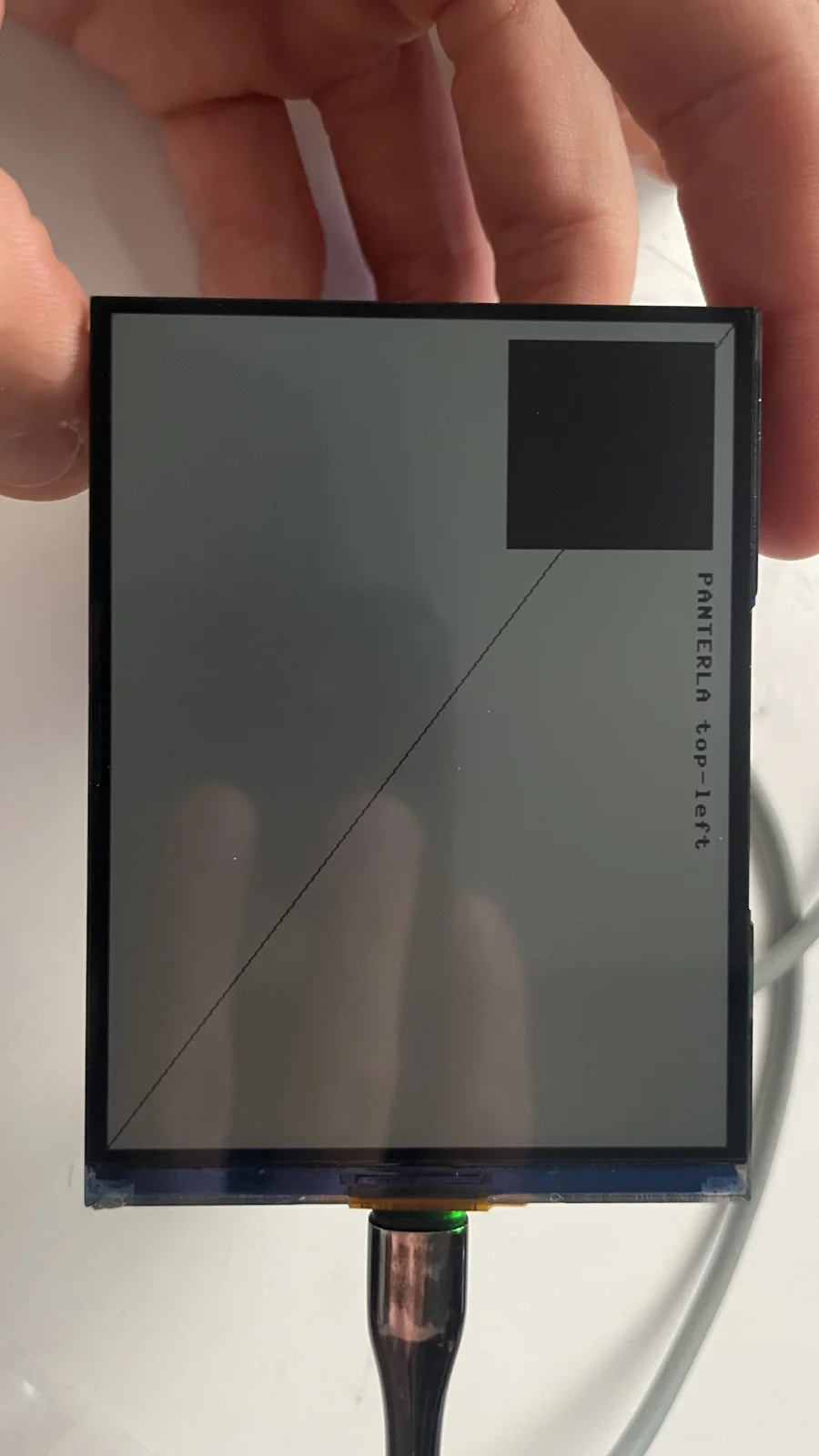
 The photograph shows the board upright, USB-C at the bottom. In the tested landscape orientation, USB-C is on the right and the buttons are on top.
The smoke test drew a one-pixel border, a diagonal from (0, 0) to (399, 299), a filled 100 × 100 px square near the top-left, and the text PANTERLA top-left.
In the upright photograph, the square appears at the top-right and the text runs vertically. Turn the image 90 degrees counter-clockwise and the intended landscape becomes clear: square at top-left, text left to right, diagonal from top-left to bottom-right. The image is not mirrored.
Was the outer pixel row missing?
The one-pixel black border could not be distinguished from the panel’s black mask in the photograph. That alone left two explanations: the outer pixels were not being displayed, or the line blended into its surroundings.
A second test drew frames inset 0, 3, 6, and 9 px. By eye, I could see the three inner frames, while the outer frame remained indistinct. A third test filled the screen black and blinked only the outermost frame white once per second. The white outline was visible at the mask boundary.
That follow-up supports the full 400 × 300 visible area, including the outer row and column. The edge-test observation was reported by eye; there are no photographs of those follow-up tests. For legibility, the practical interface should still keep text and borders a few pixels inside the edge.
What this establishes for Panterla
The tested initialization and pixel-packing port can drive this display under generic MicroPython. Its measured packing cost is small enough to continue with the interface prototype. The source record identifies the driver and smoke test at Panterla commit 3b48ecc, the inset-frame test at cf0b68c, and the blinking-edge test at 1f9bb94.
The later working motor-node prototype has since exercised KEY and BOOT, the master display, and a UART link together. That advances the integration beyond this display smoke test. A 24 MHz SPI trial, the TE signal on GPIO6, RTC, environmental sensor, microSD, and a CAN transport remain separate checks in the reviewed records.
Conclusions for the interface design
Keep generic MicroPython as the current interface platform. The tested driver and Viper packer remove the immediate reason to build custom display firmware. That is a decision about this display path; the complete recipe, storage, and communications workload still needs to earn the same confidence.
The next optimization target is responsiveness under load. After Viper reduces packing to 8.76 ms, much of the 21.5 ms full-update time is already accounted for by transmitting the frame at 10 MHz. A higher SPI clock is a possible experiment, but the application also needs to schedule drawing and transfers around input and communication work. The separate motor node keeps its step generation local; the master still needs measured response times while its display and logging are active. The roughly 46-updates-per-second calculation is a transfer-time ceiling, not an application requirement or a demonstrated operating rate.
Use the complete pixel area with a readable inset. The blinking-edge test resolved the apparent missing border, so the observed issue does not justify shrinking the driver’s coordinate range. Text and borders should sit a few pixels inside the mask, where the visual test showed them clearly. Orientation, contrast, the protective window, and the intended darkroom lighting should be checked together in the assembled interface.
The practical next gate is a sustained session with the actual interface, button input, motor status, and storage running together. Record the longest delays and missed events as well as the typical frame time. That will determine whether the present software structure is sufficient for the machine, rather than only for a test pattern.
Test record and references
The display bring-up log preserves the measured timings and the three passing smoke-test checks. Orientation and edge visibility were manual checks described above, rather than automated assertions in that log.
The manufacturer’s ESP32-S3-RLCD-4.2 documentation is the board reference. The MicroPython documentation explains the Viper code emitter. The hardware and timing values in this article come from the 2 November project probes and display tests, not from a benchmark of other boards.