Panterla’s controller now has its first working connection: the main display board sends commands to a separate motor module, the motor runs a bounded movement, and the module reports its state back. Both boards run MicroPython. The current connection is UART, with a message layout prepared for a future CAN transport.
This is the practical beginning of the modular system I want for the processor. The main board handles the operator interface and, eventually, the recipe. Local modules handle motion, heating, and fluid operations. A machine built first for drum rotation can grow without requiring every function to be fitted at once.
The video below explains that approach and demonstrates the motor prototype. The accompanying project work adds the firmware, shared command protocol, and a FreeCAD design that packages the display, power supply, controller, and motor together.
Watch on YouTube · Jump to the motor demonstration at 9:24
Waveshare supplied the ESP32-S3-RLCD-4.2 board for testing. I bought additional boards for the project, as explained in the video.
What has moved from a plan to the bench
The original October review considered an ESP32-S3 coordinator, RP2350-class nodes, and Classical CAN. The November implementation keeps the division of responsibility while starting with the hardware and link that are working now.
| Part | Current implementation | What it does today |
|---|---|---|
| Main controller | Waveshare ESP32-S3-RLCD-4.2, MicroPython 1.29 | Reflective display, motor-test buttons, commands, and received node status |
| Motor node | Waveshare RP2350-LCD-0.96, MicroPython | Local motion control and a small diagnostic screen |
| Motor driver | TMC2209 | Driver configuration and diagnostics over its own UART; motion through STEP/DIR/EN |
| Motor | NEMA 17 17HE08-1004S | Unloaded, ramped, single-revolution bench movements |
| Board-to-board link | 115200-baud UART, TX/RX and common ground | Commands and replies using shared, versioned eight-byte payloads |
| Mechanical packaging | Native FreeCAD control-unit assembly | Placement of the electronics, display stand, internal motor, and enclosure parts |
The motor node here is the RP2350-LCD-0.96, rather than the RP2350-CAN board considered in the earlier review. Its small screen is useful inside the electronics compartment: I can inspect motion state and test a module without depending entirely on the front panel.
The current first version is drum rotation only. A heater module, temperature sensing, pump control, agitation sequences, and the complete process runner remain development work. The earlier bottle warm-up tests inform the eventual readiness logic, but that logic is not yet integrated into this controller.
One main interface, local control where the work happens
The main board should ask for an outcome, such as a drum speed or a temperature target. The local module should carry out the operation, monitor its own hardware, and report what happened.
That boundary makes different machine configurations possible. One build might need only a drum drive and use an external temperature controller. Another could add the heater and fluid modules. Replacing the main display board should mean adapting the interface and communications, while retaining a working motor module and its local control logic.
There is also a practical service benefit. A technician can read the small display inside the control box, check the module’s state, and isolate a problem without replacing the whole controller. The motor-node screen already runs during motion. Similar local temperature diagnostics and service controls are an intention for the future heater module.
The local controller is autonomous in the sense that it generates and completes the commanded movement itself. It still needs a defined policy for communication loss, reset, and recovery. The present finite-motion prototype does not establish those policies for a continuously running machine.
Why MicroPython on both boards
The project switched from the earlier CircuitPython proposal to MicroPython on 2 November. On the master, the generic octal-PSRAM build runs the ST7305 reflective display. Viper packing makes a full-frame update practical without a custom display firmware build: the measured repack-and-send time was 21.5 ms at 10 MHz SPI. The display bring-up article covers that test and the visible-edge checks.
On the motor node, MicroPython provides the application logic while the RP2350’s PIO generates step pulses. DMA supplies a complete bounded motion profile, so the application does not have to feed every small group of steps while also drawing the screen and reading driver status. This addresses the visible pauses found in an earlier approach that fed motion in chunks.
Using the same language on both boards keeps the firmware easier to read and develop. The framing and motor-state code are shared between the boards and can also run in host tests. In the video I discuss using AI assistance during development; the useful result is code whose rules can be inspected and tested separately from the hardware.
The reflective main display has no backlight, which is why it is attractive for the darkroom interface. That feature alone does not qualify the complete assembly for every photographic material: board indicators, the enclosure, and use under the intended safelight still need checking. The CAD design puts the display behind a protective window because the bare board is not a sealed front panel.
The link works today over UART
The bench connection uses three wires: TX, RX, and common ground. The master sends from GPIO2 to node GP21 and receives on GPIO1 from node GP20, at 115200 baud, 8N1.
There are two different UART connections in the prototype. One connects the master to the motor node. The other lets the motor node configure and read the TMC2209. The driver’s motion inputs are still STEP, DIR, and EN; motor steps do not arrive as UART commands from the main board.
The shared protocol already separates the application message from its transport. A message has an identifier in the standard 11-bit CAN range and an eight-byte payload. For the current UART connection, a synchronization marker, identifier bytes, and CRC wrap that message into a 13-byte serial frame. The receiver checks the frame and can resynchronize after malformed input.
That makes a later transport change possible while preserving the application payload. It does not make this serial cable a CAN bus: UART has no CAN arbitration or CAN physical layer. The current setup is one point-to-point connection, not a tested multidrop network.
| Command or state | Implemented behaviour |
|---|---|
SET | Store speed and direction without starting motion |
START | Start only from IDLE, after a fresh SET with a nonzero speed |
| Immediate repeated sequence | Reply again without executing the movement twice |
STOP | Always act, including a repeated STOP; disable before replying |
STATUS | Return state, sequence, configured speed/direction, and fault information |
NOT_READY / FAULT | Refuse a new start until the required state permits it |
Replies echo the command sequence, and periodic status is sent every 500 ms. These rules are implemented for the motor prototype. A reset epoch, a node-side command lease, and the transaction rules for future FILL, DRAIN, and MOVE operations still need design and testing.
What the motor demonstration proves
In the video, pressing the master’s button starts the motor, the displays show the movement, and the node returns to idle. In the current test application, KEY sends SET 37.5 rpm followed by START, while BOOT sends STOP. The master also sends STOP during startup.
A START currently means one ramped shaft revolution, followed by idle. The 37.5 rpm value is commanded, calculated from the configured step rate and microstep setting. Shaft speed and returned shaft position were not independently measured. The video’s 75 rpm drum rotation is the intended application discussed near the end, rather than an established loaded operating result from this test.
The 2 November bench records add the following observations:
| Check | Recorded observation | Limit of the result |
|---|---|---|
| Unloaded ramped movement | 2,851 ms versus a nominal 2,839 ms profile | Move duration, without independent shaft-speed or position measurement |
| Motor-node screen during motion | Movement continued; worst recorded screen frame was 35 ms | Screen work can delay application-level response |
| STATUS request/reply | 9 ms round trip; zero CRC errors in the recorded link test | One bench configuration, without a worst-case latency distribution |
| Master button commands | START replies 37–38 ms; STOP replies usually 6–7 ms, once 32 ms during a screen frame | Reply timing, not measured STOP-to-disable or mechanical stopping time |
The motor sounded quiet and moved smoothly in the demonstration and workshop observations. There is no acoustic measurement behind that description. Likewise, a command reply does not measure how quickly a loaded drum stops.
Continuous rotation is the next motion stage. It needs a nonblocking run mode, a node-side response to lost communication, further thermal testing, and measured stopping behaviour. The current master marks old status as a lost link on its screen; that UI indication is not a motor-node shutdown mechanism.
Putting the prototype into a control box
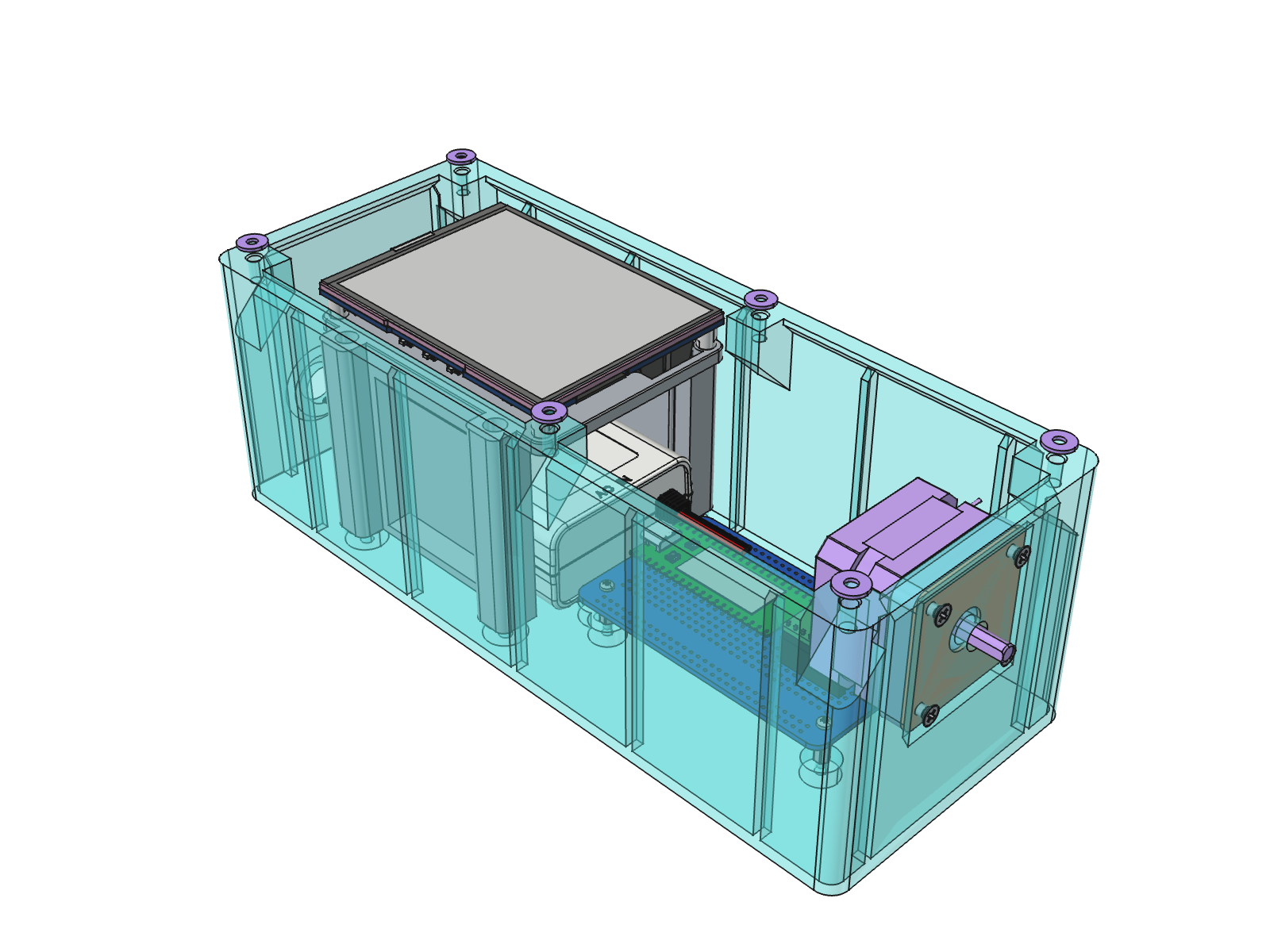
The electronics now have a physical layout in the OpenDevMachine FreeCAD project. The ControlUnit assembly brings together the enclosure, screen stand, protoboard, power supply, controller boards, and motor.
 Control-unit CAD assembly. The box is transparent and its lid and window are hidden to show the layout. This is a model of the packaging, rather than a photograph of a completed enclosure.
The reflective display sits at the front-left, on a printed stand above a Mean Well APV-35-24, 24 V / 1.5 A power supply. The RP2350-LCD-0.96 and TMC2209 share an ElectroCookie Half protoboard to the right. The NEMA 17 motor sits inside the box above the controller, with its shaft leaving through the right wall.
The enclosure design includes a 3 mm acrylic display window, a lid-groove TPU cord, washers under the lid screws, and a PG7 gland for the mains lead. At the motor exit, the proposed sealing arrangement uses an NBR oil seal in a printed flange with a TPU gasket. These are design provisions; their assembled sealing performance has not been established.
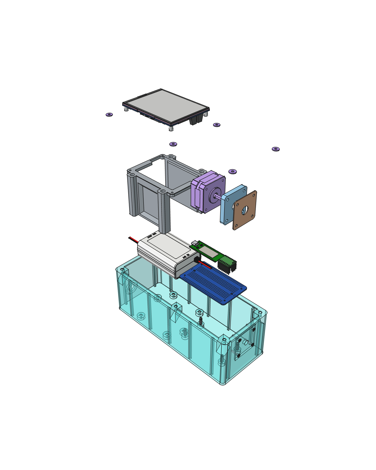 Exploded CAD view of the same unit. The separate parts show how the display support, electronics, and motor mount fit within the enclosure.
The planned external drive is a 1:1 GT2 belt to a magnetic coupling. The tank-side magnetic drive and drum supports still need design. The motor integration has been checked in the CAD assembly, but print fit, sealing, operating temperatures, and enclosure strength at the increased height remain physical validation work.
This packaging follows the same modular idea as the firmware. The display, controller, driver, and supply are identifiable parts with accessible interfaces. Keeping those interfaces understandable matters more than committing the project to one permanent custom electronics board.
Where CAN and the other modules fit next
Classical CAN remains a future transport candidate. The ESP32-S3 has a TWAI controller that requires an external transceiver; see Espressif’s TWAI documentation. The current RP2350-LCD board would also need a CAN interface. The project reserves pins for a candidate MCP2515 interface, but has not demonstrated a CAN link between these two boards.
The earlier RP2350-CAN and CircuitPython driver review belongs to the design history. It should not be read as the hardware or runtime used in the video. Bit rates of 500 and 250 kbit/s remain test candidates, and the old approximately 1 s communication-loss timeout remains an unvalidated proposal.
The next heater module is intended to combine temperature sensing, heater control, and switching of the mixing pump. The video shows components and explains that intention; the current motor firmware does not implement it. Wi-Fi dashboards, a Bluetooth app, phone-based recipe editing, and updating other nodes from the master are also future possibilities discussed in the video, without a completed implementation in the reviewed project state.
Heater protection and emergency stop must retain an independent hardwired path. Local firmware fault handling is useful, but it cannot establish that a failed power switch has removed heater power. That requirement remains part of the electrical design and commissioning work.
The validation plan now has a starting point
The original A1–A5 plan remains useful, with the UART demonstration providing partial evidence for the first integration step.
| Test | Progress and next evidence |
|---|---|
| A1 — Master integration | Display, buttons, and one motor-node link work together. Add logging and the intended workload, then record missed inputs and delays. |
| A2 — Communication timing | Initial UART round trips are recorded. Measure worst-case behaviour and STOP-to-EN latency; validate CAN separately if adopted. |
| A3 — Fault response | Motor startup and command rules are implemented. Inject resets, brownouts, cable loss, and driver/sensor faults; record outputs through recovery. |
| A4 — Drum/lift partition | A single motor node is the current scope. Add a separate lift controller only when motion, wiring, or fault behaviour justifies it. |
| A5 — Recipe and recovery | The motor state machine and frame codec have host tests. Complete recipes, interrupted fluid operations, and cross-node recovery remain open. |
Conclusions for the next controller build
The master/node division is now worth retaining. The demonstration connects an operator action, a locally generated movement, and a returned state through one defined interface. PIO and DMA handle the bounded step profile while application code handles commands and diagnostics. This establishes a useful first module to build on; adding heater and fluid nodes still requires their own feedback and failure rules.
Keep the working UART link while validating the next motion stage. It already supports the current one-master/one-node bench setup. Moving to CAN should answer a demonstrated wiring, node-count, or fault-handling requirement and include its own timing tests. Preserving the application payload helps reuse code, while the physical network and recovery behaviour remain work to validate. A bus change alone would not resolve the missing continuous-motion and communication-loss policies.
The next motion milestone is loaded, continuous operation with a measured stop response. Before extending a short bounded move into a long run, implement and test the node’s response to stale commands and loss of the master. Measure from the stop request to driver disable and then to the loaded mechanism stopping, including the longest delay during screen activity. The recorded reply times are a starting observation for that work. The drum-drive study supplies the load and mechanical questions.
The future temperature module needs to report process readiness. The bottle experiments show that bath temperature alone is insufficient. The master will need to distinguish initial warm-up, refill recovery, and a verified hold condition for the liquids required by a recipe. A live heartbeat and an old temperature value must not be presented as current readiness. The required sensor coverage, acceptable band, and hold interval remain to be defined and tested.
The CAD layout makes the packaging concrete enough to test next. In particular, putting the motor and supply inside the same box creates a reason to measure enclosed operating temperatures as well as printed fit and sealing. The next controller build should therefore combine the representative drum load, real enclosure, active displays, and communication logging. Separate successful bench checks become evidence for a usable processor only when those parts work together over the intended operating cycle.
Evidence: the linked architecture video and its supplied automatic subtitles; the OpenDevMachine project decisions, current master application, motor-node implementation, shared frame codec, and recorded 2 November hardware checks; and the control-unit CAD documentation and exported images reviewed through 7 November. Automatic-caption board-name errors are resolved against the project records. Timings quoted here are recorded development observations, not newly repeated measurements or finished-machine specifications.